Description
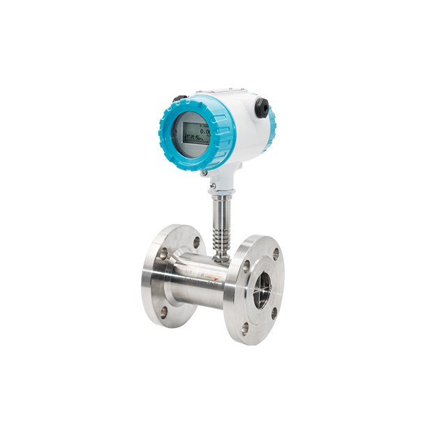
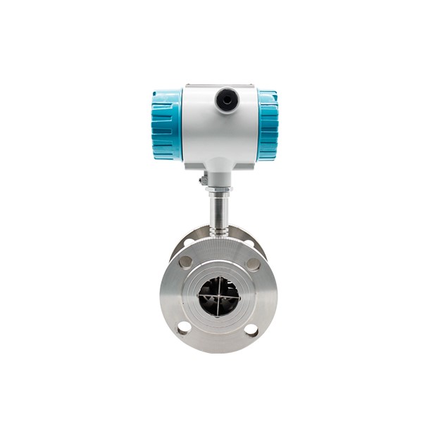
Turbine Liquid Flow Meter | LWGY
Table 1: Liquid Turbine Flow Meter Parameters
| Size & Process Connection |
Thread connection: DN4, 6, 10, 15, 20, 32, 40, 50, 65, 80, 100
Flange connection: DN15, 20, 32, 40, 50, 65, 80, 100, 125, 200
Clamp connection: DN4, 6, 10, 15, 20, 32, 40, 50, 65, 80, 100 |
| Accuracy |
±0.5%, ±0.2% Optional |
| Sensor Material |
SS304, SS316L Optional |
| Ambient Conditions |
Medium temperature:-20℃~+150℃
Atmospheric pressure:86Kpa~106Kpa
Ambient temperature:-20℃~+60℃
Relative humidity:5%~90% |
| Signal Output |
Pulse, 4-20mA, Alarm(optional) |
| Digital Communication |
RS485, MODBUS; HART |
| Power Supply |
24V DC/3.6V Lithium Battery |
| Cable Entry |
M20*1.5; 1/2″NPT |
| Explosion-proof class |
Ex d IIC T6 Gb |
| Protection class |
IP65; IP67 Optional |
Table 2: Liquid Turbine Flow Meter Dimension .jpg)
| Diameter |
Flange Connection |
| (mm) |
L(mm) |
D(mm) |
K (mm) |
d (mm) |
n (Holes) |
Flange Thickness C (mm) |
| 10 |
345 |
90 |
60 |
14 |
4 |
16 |
| 15 |
75 |
95 |
65 |
14 |
4 |
16 |
| 20 |
80 |
105 |
75 |
14 |
4 |
18 |
| 25 |
100 |
115 |
85 |
14 |
4 |
18 |
| 32 |
120 |
140 |
100 |
18 |
4 |
18 |
| 40 |
140 |
150 |
110 |
18 |
4 |
19 |
| 50 |
150 |
165 |
125 |
18 |
4 |
21 |
| 65 |
175 |
185 |
145 |
18 |
4 |
21 |
| 80 |
200 |
200 |
160 |
18 |
8 |
23 |
| 100 |
220 |
220 |
180 |
18 |
8 |
23 |
| 125 |
250 |
250 |
210 |
18 |
8 |
25 |
| 150 |
300 |
285 |
240 |
22 |
8 |
25 |
| 200 |
360 |
340 |
295 |
22 |
12 |
27 |
Table 3: Liquid Turbine Flow Meter Flow Range
Diameter
(mm) |
Standard Range
(m3/h) |
Extended Range
(m3/h) |
Connection Standard(Optional) |
Standard Pressure
(Mpa) |
Customised Pressure Rating(Mpa) |
| DN4 |
0.04~0.25 |
0.04~0.4 |
Thread |
6.3 |
12,16,25…42 |
| DN6 |
0.1~0.6 |
0.06~0.6 |
Thread |
6.3 |
12,16,25…42 |
| DN10 |
0.2~1.2 |
0.15~1.5 |
Thread |
6.3 |
12,16,25…42 |
| DN15 |
0.6~6 |
0.4~8 |
Thread (Flange) |
6.3,2.5 (Flange) |
4.0,6.3,12,16,25…42 |
| DN20 |
0.8~8 |
0.45~9 |
Thread (Flange) |
6.3,2.5 (Flange) |
4.0,6.3,12,16,25…42 |
| DN25 |
1~10 |
0.5~10 |
Thread (Flange) |
6.3,2.5 (Flange) |
4.0,6.3,12,16,25…42 |
| DN32 |
1.5~15 |
0.8~15 |
Thread (Flange) |
6.3,2.5 (Flange) |
4.0,6.3,12,16,25…42 |
| DN40 |
2~20 |
1~20 |
Thread (Flange) |
6.3,2.5 (Flange) |
4.0,6.3,12,16,25…42 |
| DN50 |
4~40 |
2~40 |
Thread (Flange) |
2.5 |
4.0,6.3,12,16,25…42 |
| DN65 |
7~70 |
4~70 |
Flange |
2.5 |
4.0,6.3,12,16,25…42 |
| DN80 |
10~100 |
5~100 |
Flange |
2.5 |
4.0,6.3,12,16,25…42 |
| DN100 |
20~200 |
10~200 |
Flange |
1.6 |
4.0,6.3,12,16,25…42 |
| DN125 |
25~2500 |
13~250 |
Flange |
1.6 |
2.5,4.0,6.3,12,16…42 |
| DN150 |
30~300 |
15~300 |
Flange |
1.6 |
2.5,4.0,6.3,12,16…42 |
| DN200 |
80~800 |
40~800 |
Flange |
1.6 |
2.5,4.0,6.3,12,16…42 |
Table 4: Liquid Turbine Flow Meter Model Selection
| Model Suffix Code |
Description |
| LWGY- |
XXX |
X |
X |
X |
X |
X |
X |
X |
X |
| Diameter |
|
|
|
|
|
|
|
|
Three Digitals; for example:
010: 10 mm; 015: 15 mm;
080: 80 mm; 100: 100 mm |
| Converter |
N |
No display; 24V DC; Pulse Output |
| A |
No display; 24V DC; 4-20mA Output |
| B |
Local display; Lithium Battery Power; No output |
| C |
Local display; 24V DC Power; 4-20mA Output; |
| C1 |
Local display; 24V DC Power; 4-20mA Output; Modbus RS485 Communication |
| C2 |
Local display; 24V DC Power; 4-20mA Output; HART Communication |
| Accuracy |
05 |
0.5% of Rate |
| 02 |
0.2% of Rate |
| Flow Range |
S |
Standard Range: refer to flow range table |
| W |
Wide Range: refer to flow range table |
| Body Material |
S |
SS304 |
| L |
SS316 |
| Explosion Rating |
N |
Safety Field without Explosion |
| E |
ExdIIBT6 |
| Pressuring Rating |
E |
Per Standard |
| H(X) |
Customized Pressure Rating |
| Connection |
-DXX |
DXX: D06, D10, D16, D25, D40 D06: DIN PN6; D10: DIN PN10 D16: DIN PN16; D25: DIN PN25 D40: DIN PN40 |
| -AX |
AX: A1, A3, A6
A1: ANSI 150#; A3: ANSI 300#
A6: ANSI 600# |
| -JX |
|
| -TH |
Thread; DN4…DN50 |
| Fluid Temperature |
-T1 |
-20…+80°C |
| -T2 |
-20…+120°C |
| -T3 |
-20…+150°C |
Turbine Liquid Flow Meter | LWGY
Brand
Royce Water Systems




Reviews
There are no reviews yet.